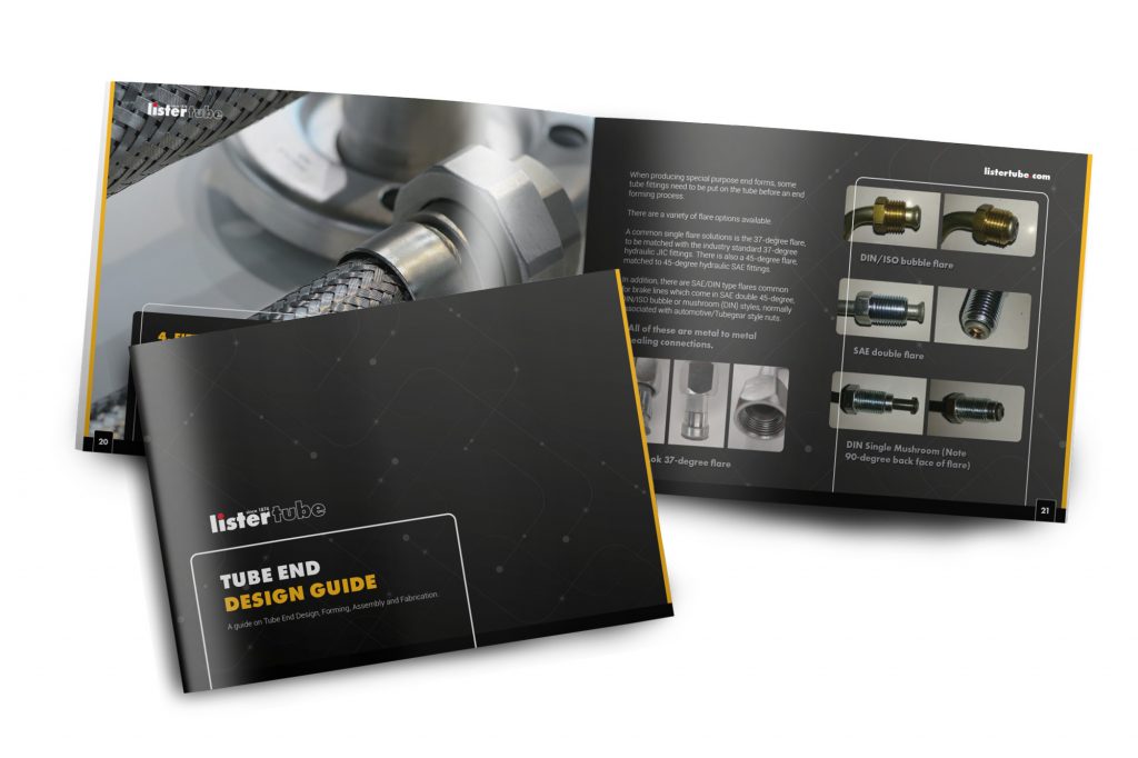
This supplement to our very popular tube bending guide explains the wide range of tube end forming, assembly and fabrication processes. By ensuring that product developers are aware of what is available and some of the considerations, they can prepare manufacture-ready designs utilising the most suitable design features.
Purposes of tube end forms
What do we mean by a tube end form? Quite simply it can refer to any shape that we cut or form on the end of a tube. Technically, even a square saw cut is a plain end form. However, it can then undergo forming processes to achieve a required special shape. These shapes or special purpose end forms allow the tube to be joined to fittings, hoses, or other tubes or components, for many applications including fluid or gas transfer, or for mechanical assembly.
1. To create a mechanical fixing
This can be between the tube and another piece of tube, or with another component, and it can be permanent, semi-permanent or temporary. There are various options to consider for these different cases.
2. To provide a liquid tight seal joint for fluid transfer
This can be between the tube and another tube, hose, manifold or fitting. These typically involve some type of flaring of the end of the tube and are what people often mean when they use the term “end-form”.
Mechanical Fixing – Tube Fabrication
Many fabrication processes can be applied to straight or manipulated tubing to prepare them for mechanical/structural assembly. The processes usually involve the removal of material, whether by cutting, sawing, machining, drilling etc. These features on the tube can be used during assembly or further fabrication (welding and brazing).
1. Notching
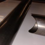
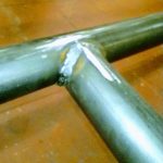
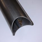
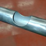
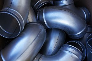
Often known as cod-mouthing (due to the shape which is reminiscent of a fish’s open mouth) when performed on the end of the tube. This is commonly used when tubes are to be permanently joined together as part of a welded or brazed fabrication. The angle and diameter of the cut can be altered to suit. Tubes can be notched along their length also.
This end form can also be used for a semi-permanent fixing by welding a nut inside the notched end and drilling a hole through the other tube. A bolt can then be passed through the hole and screwed into the nut. This is often used in furniture joints.
2. Mitre Cutting
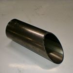
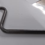
The end of the tube can be cut at any angle up to 45 degrees on a cold saw; past this angle it would require machining. Tubes are usually mitre cut after bending. It is also possible to cut through the bend.
3. Flattening
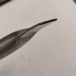
This method involves flattening the end of the tube. For mechanical/structural applications, there may be a hole drilled through to allow securing to whatever it needs to be attached to. The corners of the flattened piece can be chamfered or rounded off.
This appears to be a very simple end form, but just hitting the end with a hammer will not produce a very attractive result. To produce a repeatable form, a fly-press, or better a hydraulic press, is needed. For best results, especially where an aesthetic finish is needed, a shaped press tool is required. Sometimes, these tools can be 3D printed, thus keeping costs to a minimum whilst producing a great looking form.
This end form is often used for structural purposes, and it is also possible to flatten a tube partway along, possibly even after bending, for more complicated structures.
Flattened ends can also be used as nozzles or sprayers.
4. Swaging or expanding
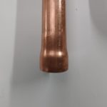
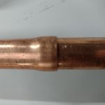
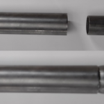
A swaged end form is where a tube end is swaged or crimped down to a specified dimension, with the aim of reducing the outside diameter. The application for this could be for a tube to slide into another piece of the same tube. An expansion is the opposite; the end is expanded out to increase the internal diameter.
These end forms are ideal for assembling multiple tubes. This may be a brazed/welded connection or mechanical/structural assembly. This approach is well suited to temporary tube joining applications or where a kit of parts could be provided in flat pack form and easily assembled by the end user.
5. Thread-forms and Flow-drilling
Thread forms can be used for either a mechanical joint or for fluid connection.
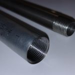
A thread form can be cut into the end of a tube, ID or OD, although it does require a sufficient wall thickness, which brings with it added cost and weight. This is usually done on a lathe before bending of the tube. There can be challenges with this, such as the difficulty of machining a thread onto the end of a long piece of tube and, depending on how the tube is to be bent, ensuring the exact developed length, since in this scenario there can be no cutbacks. Therefore, if an end thread is required, a threaded end fitting, connected by using one of the flared solutions explained in the next section, may be more appropriate.
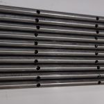
Although not exactly an end form, it is also worth mentioning holes along the length of a tube. Drilling of tube can be done manually, with a jig with drill bushes or on a milling machine. These drilled holes can be tapped afterwards if necessary.
Slots can be added to the tube by milling or laser cutting.
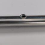
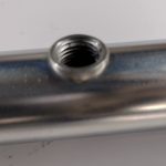
There is also a very useful process known as flow-drilling and tapping.
Unlike drilling, where material is removed, flow-drilling is a specialised technique that allows a hole to be created by hot forming the material. The material is pushed into a cone shape that can then be roll tapped. As you can see from the illustration, this provides many more thread turns, thus providing a much more secure connection. This technique is often used for producing manifolds and is a very cost effective and compact way of joining a set of pipes or hoses together.
Fluid Transfer End Forms
1. Simple nut and olive
Here there is no forming done on the tube. An “olive”, otherwise known as a ferrule, or sometimes a cutting ring, is compressed onto the tube between a tube nut (female thread), and a male-threaded end fitting (itself ready to connect to another hose, tube or bulkhead).
It requires care to ensure that the ferrule is seated properly, and the thread tightened to exactly the right amount to avoid a leak path. Some of the end forms detailed below, which rely on an extremely accurately formed flare on the tube end, are much better suited to leak-free solutions, especially in higher pressure applications.
Firstly though, we consider two other end forms designed for simple tube to hose connections, that can be made “in the field” with either no tools or a simple screwdriver.
2. Beading
One of the simplest end forms is the bead. A bead is a raised ring of material around the tube usually used to retain a flexible hose with a clip (jubilee). In production, beading can be done on automated punch type machines or on pinch roller dies before or after bending, dependant on the design and tooling availability.
In use, typically a flexible hose is pushed over the tube end, over the bead and is secured with a hose clamp (which many people generically call a Jubilee Clip).
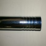
3. Special machining of hose tail ends
Sometimes known as a fir tree form, this is a simple push fit end form. A flexible hose with a tight interference fit is pushed over the hose tail and relies on friction to keep it in place. It is very simple to use because no tools are required to create the joint.
This is a common solution for very low-pressure applications where machined end fittings can be used. It is more challenging as a tube end form since the serrations need to be machined onto the tube. It requires a reasonably thick-walled tube to allow sufficient material for machining. An alternative solution, sometimes used on long tube lengths where this form is required, is to braze or weld a serrated hose tail machined fitting onto the end of the tube.

4. Fitting Related End Forms
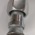
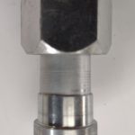
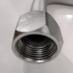
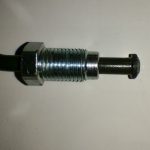
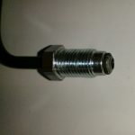
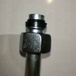
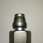
This approach is the mainstay of end-forming used for fluid transfer joints and is a development on from the simple nut and olive solution. In simple terms, a nut (and in some cases a sleeve) is slid onto the tube and then the end of the tube is flared. This both captivates the nut/sleeve and allows the nut/sleeve to be pushed up against the flare to make a joint by screwing it onto the male thread of another tube/hose line or manifold. The external face of the flare forms a seal against the nose of the male threaded fitting.
When producing special purpose end forms, some tube fittings need to be put on the tube before an end forming process.
There are a variety of flare options available.
A common single flare solutions is the 37-degree flare, to be matched with the industry standard 37-degree hydraulic JIC fittings. There is also a 45-degree flare, matched to 45-degree hydraulic SAE fittings.
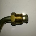
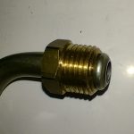
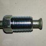
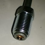
In addition, there are SAE/DIN type flares common for brake lines which come in SAE double 45-degree, DIN/ISO bubble or mushroom (DIN) styles, normally associated with automotive/Tubegear style nuts.
All of these are metal to metal sealing connections.
To provide much higher leak-free confidence, especially in applications where there may be excessive vibration or variable pressure, such as pulsing, there are a range of soft seal solutions, suitable for 6mm – 38mm standard hydraulic tube sizes.
Higher pressure tube fittings require pre-assembly, sometimes using special purpose equipment such as the Parker DIN or EO2 hydraulic tube fittings. The ring is crimped onto the tube, and EO2 fittings have a soft seal for better sealing.
In the case of ORFS (which stands for O Ring Face Seal), the seal is, as the name suggests, in a groove in the face of the male fitting, that the tube end form is pulled against, by the captive female UNF threaded nut.

