DOWNLOAD THIS GUIDE
DOWNLOAD
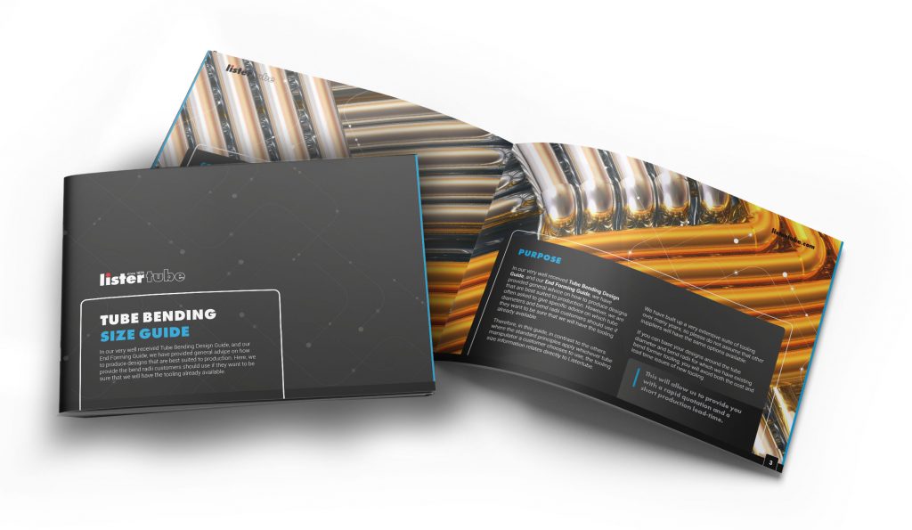
Purpose
In our very well received Tube Bending Design Guide, and our End Forming Guide, we have provided general advice on how to produce designs that are best suited to production. However, we are often asked to give specific advice on which tube diameters and bend radii customers should use if they want to be sure that we will have the tooling already available. Therefore, in this guide, in contrast to the others where the standard principles apply whichever tube manipulator a customer chooses to use, the tooling size information relates directly to Listertube.
We have built up a very extensive suite of tooling over many years, so please do not assume that other suppliers will have the same options available.
If you can base your designs around the tube diameter and bend radii for which we have existing bend former tooling, you will avoid both the cost and lead time issues of new tooling. This will allow us to provide you with a rapid quotation and a short production lead-time.

Tube design principles
Unless you are experienced in designing tube components, we would strongly recommend that you read our Tube Bending Design Guide. In particular, it is worth reiterating that, wherever possible, you should design your tubes with only one bend radius.
One additional point, which we are sometimes asked is what is the minimum straight length required between bends. The reason that a straight length is required is so that the tube can be held by the clamp, during draw bending, whilst it is drawn around the former. The simple answer to the question is that the straight should be no less than the bend radius, or
Minimum straight between bends at least R
It is, of course, best to leave as much space as possible. For thinner tubes or tight bends, ie. where the centre line bend radius is less than twice the diameter of the tube, the straight will need to be considerably longer, because much stronger clamping area is needed.
It is possible to operate with shorter straights, but it will often result in clamping marks being clearly visible on the finished tube, especially where it is a thin-walled tube (i.e. wall thickness is less than around 10% of the tube diameter). For best practice stick to this guideline.
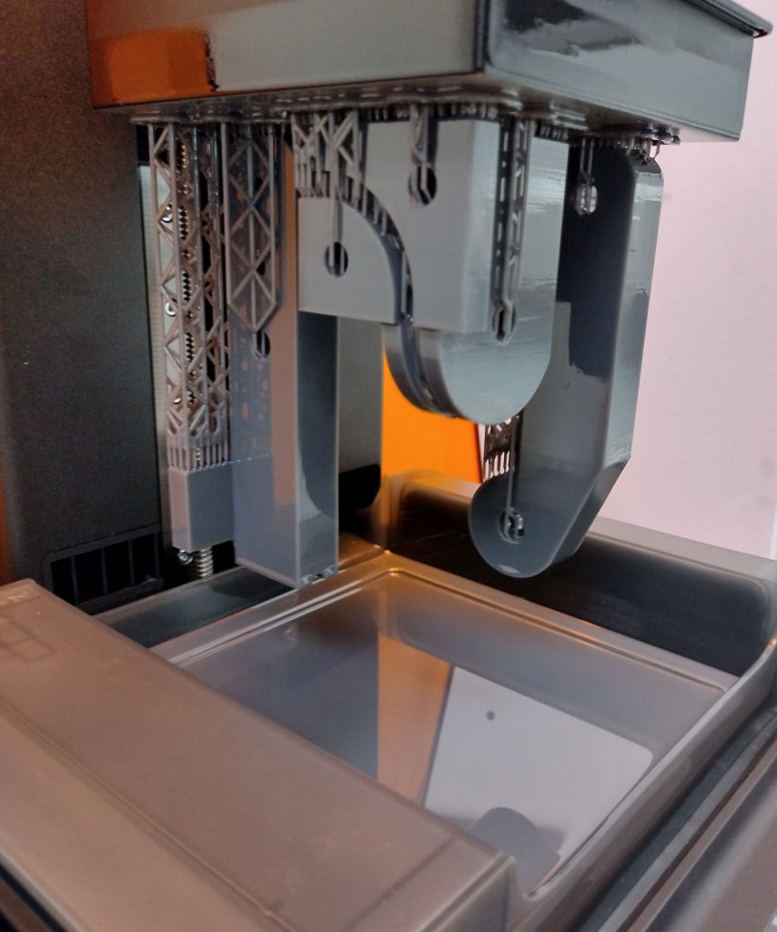
Additive manufacture print tooling
In addition to the wide range of tooling sizes that we already have on the shelf we also have the capability to produce the bend former as temporary tooling produced on an additive manufacture printer. Temporary means that it can produce some tens, or sometimes hundreds, of parts before it requires replacement. However, once we have the tool former designed, we can reprint another relatively inexpensively and quickly, and so you can consider these tools as if they are normal steel bending tools.
We have the capability to print bend formers for tubes up to around 35mm diameter, 2 mm wall thickness, based on a 2D bend radius.
Therefore, if you do require a very specific diameter/radius combination that we do not already have we may be able to manufacture it via printing rather than traditional steel toolmaking. Note, however, that the tool will still require designing first, so some cost and lead-time cannot be completely avoided.

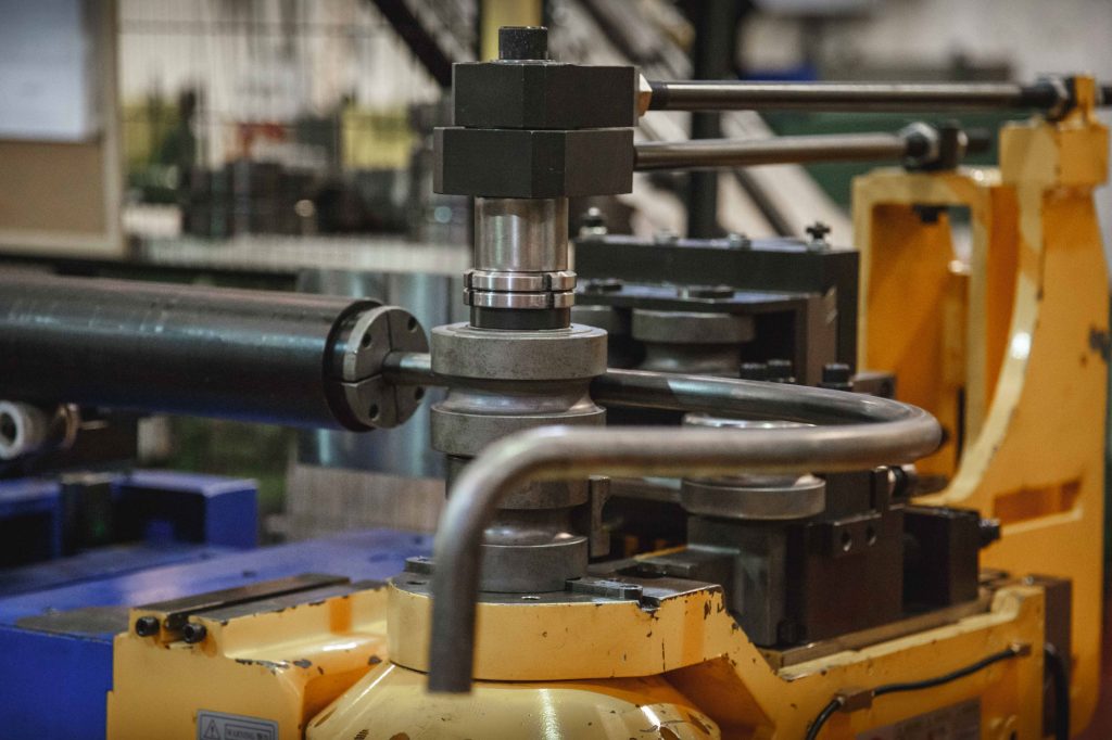
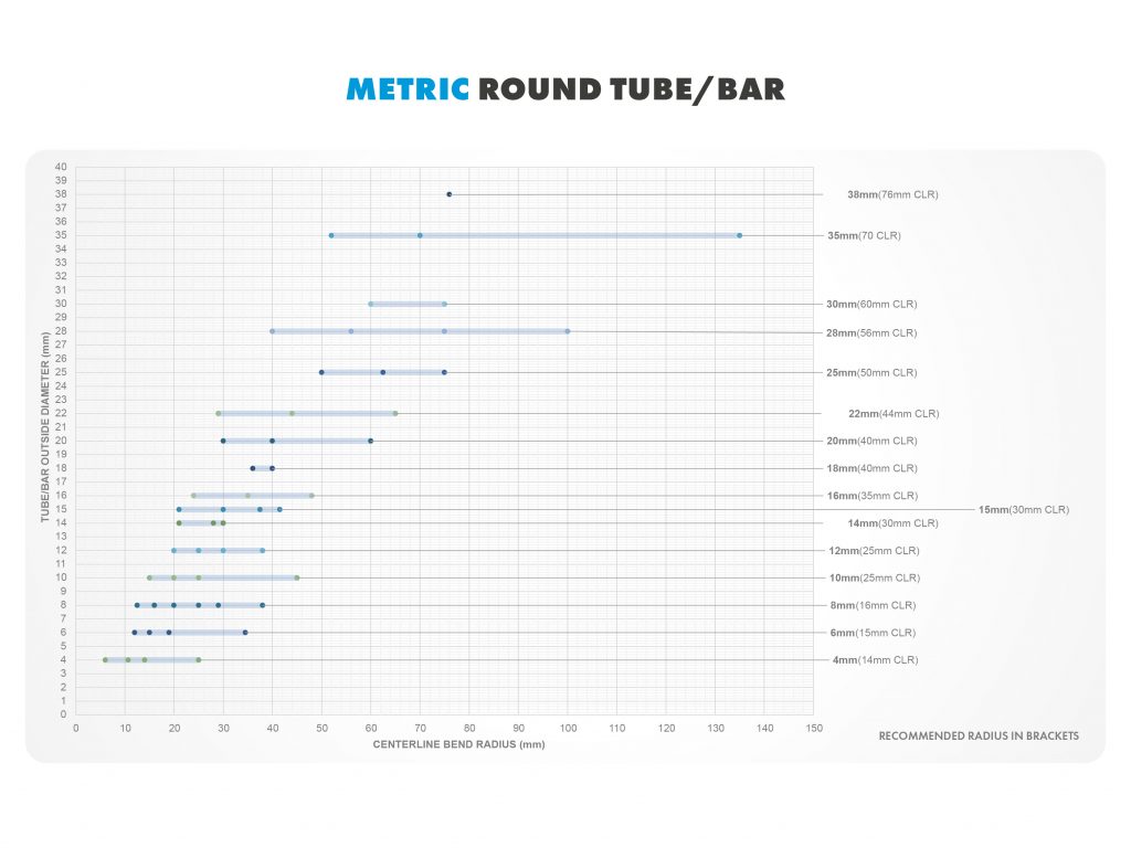
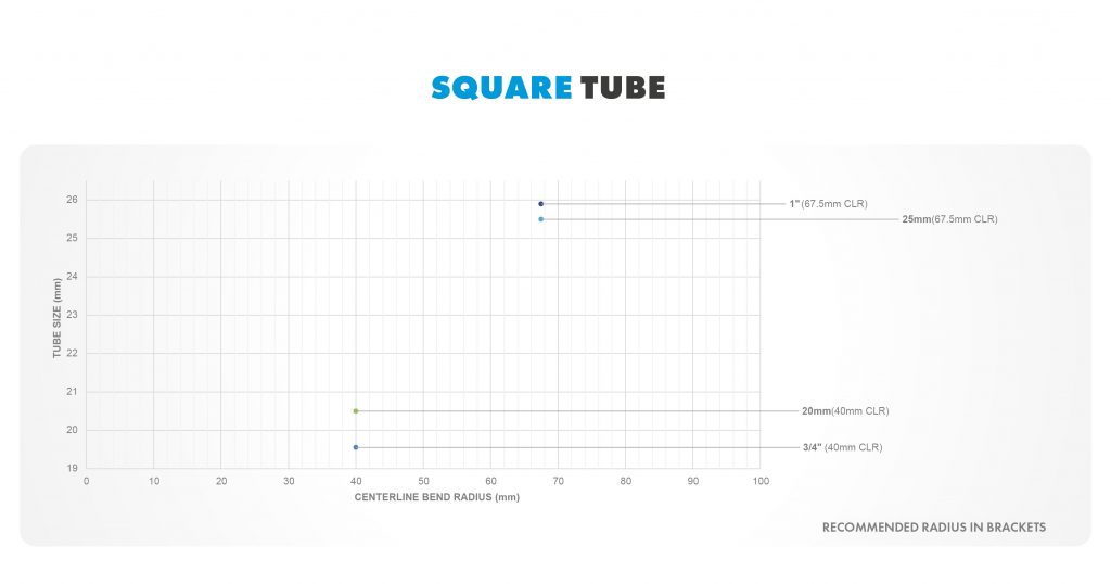
Tooling charts
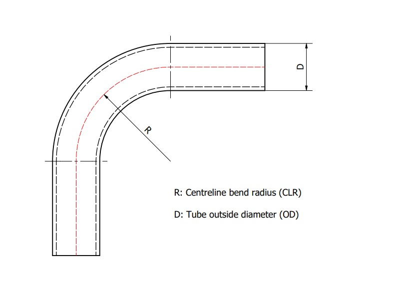
The tooling charts show the tube diameter (or the square wall size) on the vertical axis, either metric or imperial sizes. Against each diameter is a horizontal shaded bar showing the range of bend formers that we have. The numbers across the bottom of the chart refer to the radius of the bend. This is the centre line radius (CLR), i.e. the distance from the centre of the bend to the centre line of the tube. In most cases we have many tools available within the shaded range.
However, we have selected the most popular tools, highlighted as dots, with the recommended one shown in brackets on the left of the chart, to simplify the diagram, but most importantly to guide you to selecting tools which are most frequently in use on our bending machines. Selecting these tube diameter and bend radius combinations will ensure that we can offer you the shortest possible production lead-time.
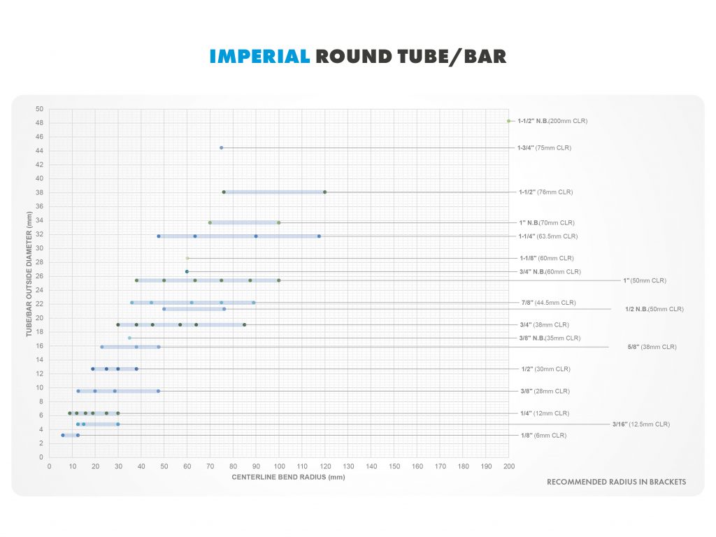
We do not mention wall thickness on the chart. This is because we can match the relevant mandrel (plug, one-ball or multiple-ball), where needed, with the bending tools so that most (available) wall thickness can be bent, with a smooth bends and no collapsing. In general, the thicker the wall and/or the larger the bend radius, the easier to bend, and hence the better the resulting component.
NOTE: these charts show the size extent of our core tooling portfolio and some suggested and recommended tube bend radii, for a particular tube diameter. However, we have many other tool sizes available, including outside the shaded bars, so please contact us for any specific requirements.
TUBE END DESIGN GUIDE
A guide on Tube End Design, Forming, Assembly and Fabrication.