Tube Optimisation Guide
DOWNLOAD THIS GUIDE
DOWNLOAD
An introduction to Tube Optimisation
As a product designer, you face an unenviable challenge.
You need to know enough about many different types of forming technologies to allow you to produce cost effective and feasible designs. The difficulty is that without having worked in some of those industries yourself, you may not be aware of some of the black art involved with some of these forming methods. Often, even the practitioners working in those sectors rely on rules of thumb.
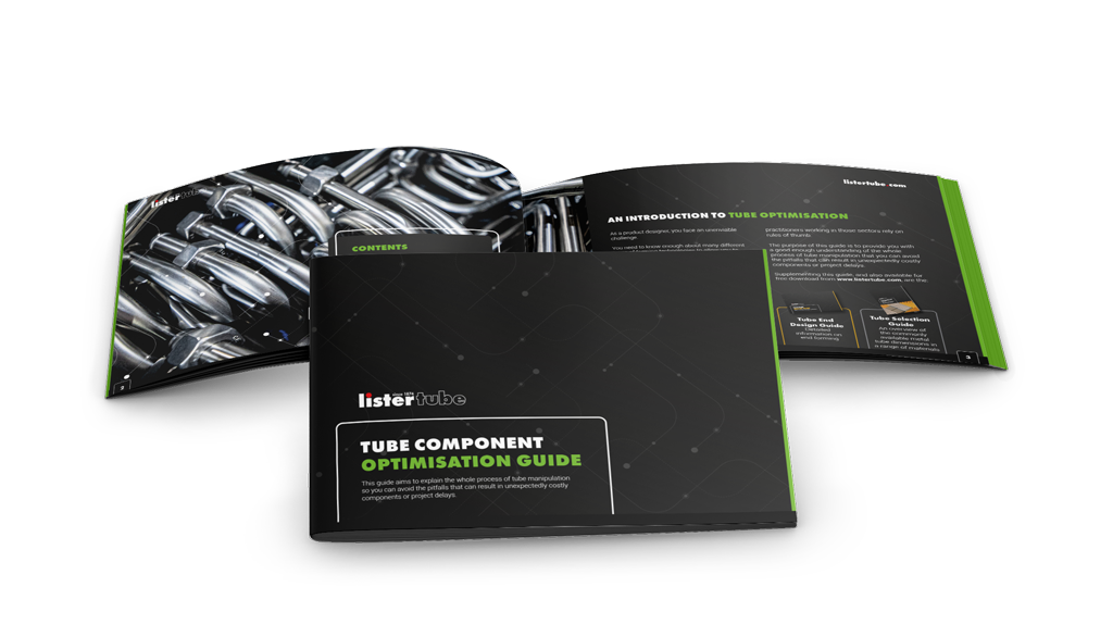
The purpose of this guide is to provide you with a good enough understanding of the whole process of tube manipulation that you can avoid the pitfalls that can result in unexpectedly costly components or project delays.
Like most things in life, once you understand tube bending, it is relatively straightforward. In fact, the following description will make it appear deceptively simple.
However, there are some key choices that you, the designer, will make that will dictate whether production is easy or more challenging, and whether the costs will be high or low.
We are going to follow the production of a typical tubular component and identify the key decision points along that journey.
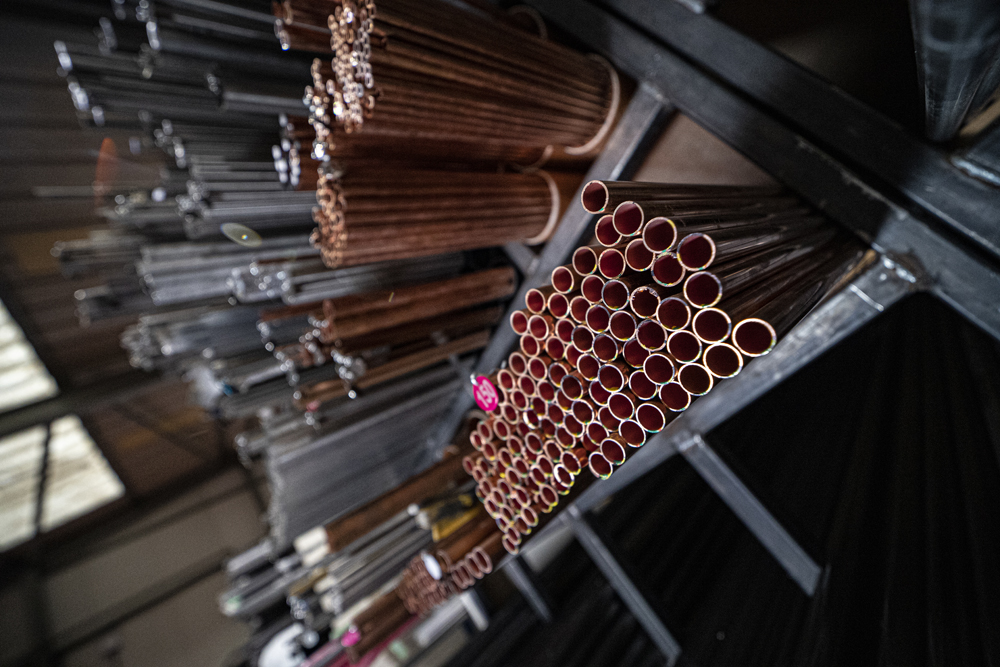
Choosing the Tube
The first step, once a production/works order arrives on the shop floor, is to fetch the tube to produce it. That immediately raises the question of the tube specification covering which material and what diameter and wall thickness. Also, is it a common selection so that we have it in stock, or do we have to source it first?
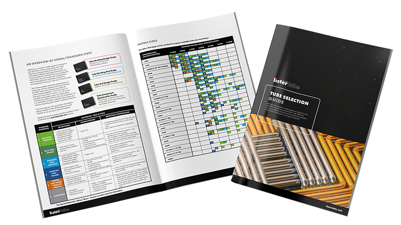
Our Tube Selection Guide will help you to select commonly available (and hence cost-effective) tube diameters/ wall thicknesses in standard materials such as mild steel, stainless steel, copper and aluminium.
*For Special Materials / Alloys / Brass – Contact our sales team for information
Due to the variety of materials available, and the wide range of size options, it can sometimes seem like a difficult task to select the correct tube.
In reality, the application itself will filter the choice down significantly – all that is needed is an understanding of the basic principles of which materials are suited to which applications, then consider what the main priorities are (normally cost, weight or corrosion resistance).
 Other factors such as pressure rating, flow rate or tensile strength, can be determined by the size and gauge (wall thickness) of the tube.
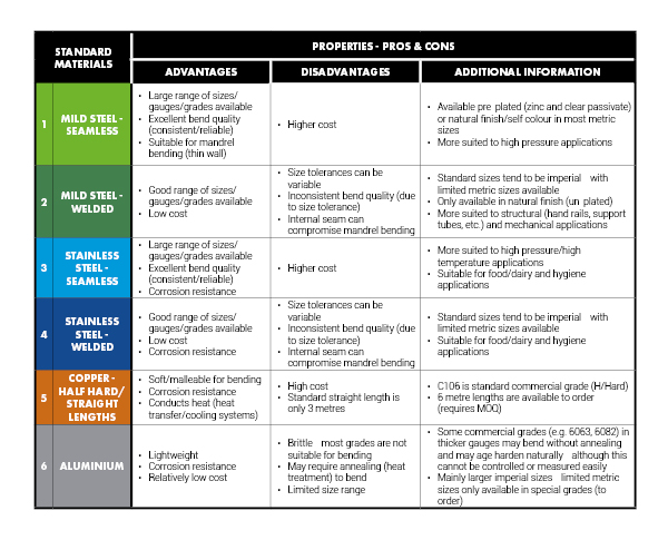
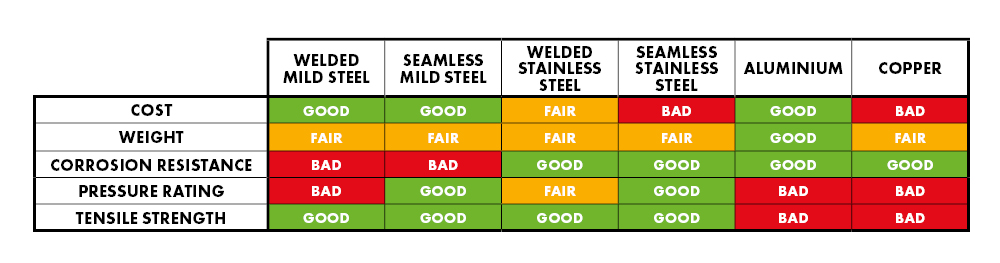
Normally, mild steel tube is the most economical option – with welded grades being cheaper than seamless (this would also apply to stainless steel tubes). Aluminium is the lightest, stainless steel offers the best corrosion resistance, and copper tube offers the best conductivity (for heat transfer/cooling systems) whilst also offering good corrosion resistance.
There may be crossovers and variables of these factors – for example, if you need a corrosion resistant, lightweight tube for a high-pressure application – a thin wall seamless stainless steel tube would be the obvious choice.
Alternatively, if you need a strong tube for a grab handle to be welded to a machine and then painted, a thick wall welded mild steel tube would be the obvious choice.
Here is a simple chart to illustrate these principles and variables.
If you need samples very quickly, just call us to see what tube options we are already holding in stock near to your preferred dimensions.
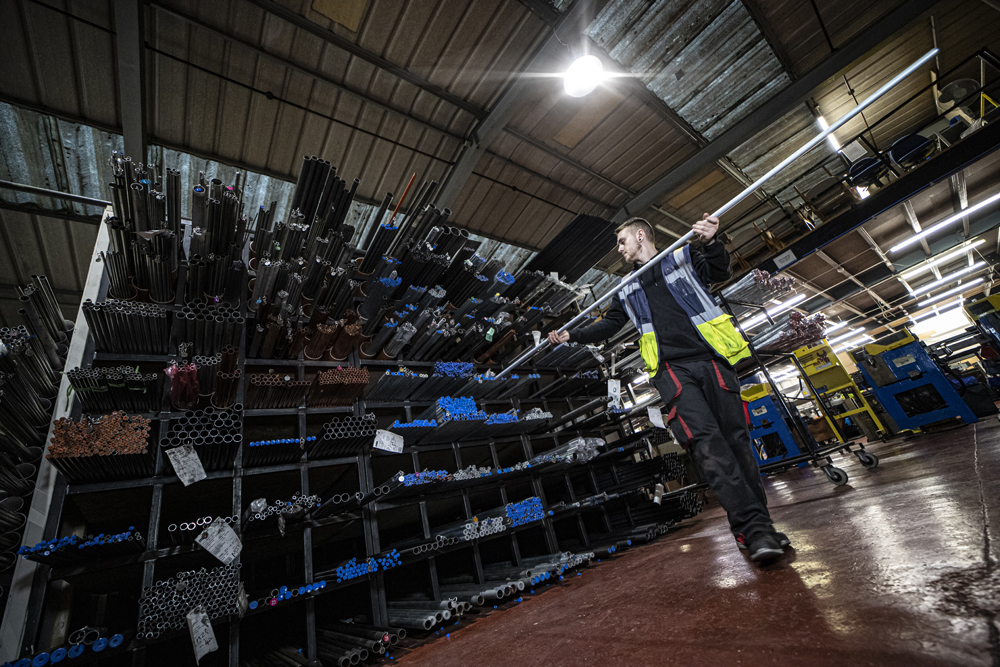
Cutting to Length
Back to the shop floor! Once we have fetched the tube from the storage rack, we will cut it into appropriate lengths.
The length will be either exactly enough to produce the finished component or just a little bit longer. Imagine taking your finished component and unbending it; you would end up with a straight piece.
Measure that and it is what we call the developed length. If there is a bend near the end, we may have to keep a short extra length of tube on the end to grip or clamp the tube whilst bending. This piece gets trimmed back later.
So clearly, wherever possible, you should design to maximise the yield, and minimise offcut waste.
Yield – Tube typically comes in 6 metre lengths
If you design your tubular component to a developed length of 2 metres (or just under), you will get 3 components per 6 metre tube length with minimal waste.
If your developed length is 2.1 metres, then you will only get 2 components from the length creating significant waste, but your tube manipulation supplier will almost certainly charge you for the full length, as they will have no way of knowing if or when they may be able to use up that remaining 1.8 metres.
Deburring
Next, we will deburr the cut ends. This is done to protect the operators’ hands as well as to provide you with a tidy component.
Deburring will typically be done with a wire wheel, or for smaller components it may be done by using ceramic media (granules) in a rumbling/vibrating machine – known as barrel deburring.
Unless you have a specific design requirement for a chamfered end, do not specify that on your drawing, otherwise your tube bending subcontractor will be forced to have the ends machined!
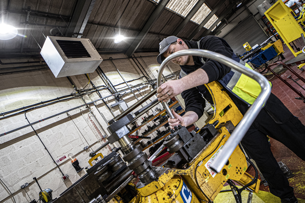
Bending
Now we are ready to bend the tube. We have written an entire guide on this topic, the Tube Bending Design Guide so it is best to refer to that for a complete understanding of the points to consider.
Here we will just consider draw (or mandrel) bending, which is one of the most common CNC bending techniques used for producing highly repeatable tight radius tube bends.
Firstly, we will need to load the relevant tooling onto the bending machine.
For draw bending, bend tooling consists of a former, which is essentially a circular block with a semi-circular groove around the outside, which the tube can sit in, along with some other components such as clamps, pressure die and perhaps another piece called a follower.
 The groove in the former has a diameter equal to that of the outside diameter of the tube we are going to bend, and the former block radius is equal to the centre line radius of the bend we want to produce. You can immediately see that if we want to create bends of more than one radius in our tube, then we will need more than one former.
That, of course, is possible, but it immediately restricts production to bending machines that have multi-stack (multi-tool) capability, and it also increases set-up time. So, unless you have a good reason to choose variable bend radii, it is always best to stick to one common radius for your bends within a component. If you will be ordering a set of tubular components, all of the same tube diameter, then it makes sense to stick to the same bend radius throughout the set, so that your tube bender can set up their machine once and produce the whole batch in one go.
Tooling can cost several thousand pounds and can take many weeks to produce. If you will be sourcing high volumes of components then this is not likely to be a problem, but if you require modest quantities, require a quick delivery, or want to produce some prototypes, then selecting a tube diameter/bend radius combination for which your tube bender already has existing tooling makes most sense.
Once the tool is on the machine, then we have to complete the set-up, getting all the machine parameters just so, to produce the required bent components.
If the job has been done before, then the CNC bending program will already have been produced and set-up will consist mainly of clamping all parts of the tooling correctly into the starting positions. If it is a new job, then the CNC bending program has to be written. If you are able to provide your tubular component design as a CAD model (STP file), this process can be considerably shortened as the XYZ bend co-ordinates can be more readily extracted from the model than from a 2D drawing.
The Listertube Tube Bending Size Guide is a good starting place to choose a reasonably standard combination, or call us and ask what options we have available near to your ideal dimensions.
Again, if it is a new job then there will be a development stage where the first-off trial piece will be measured on the co-ordinate measuring machine, and any variations from the required dimensions will be fed back to the CNC bending machine so that subsequent pieces will be correct.
This allows correction, for example, of springback of the tube.
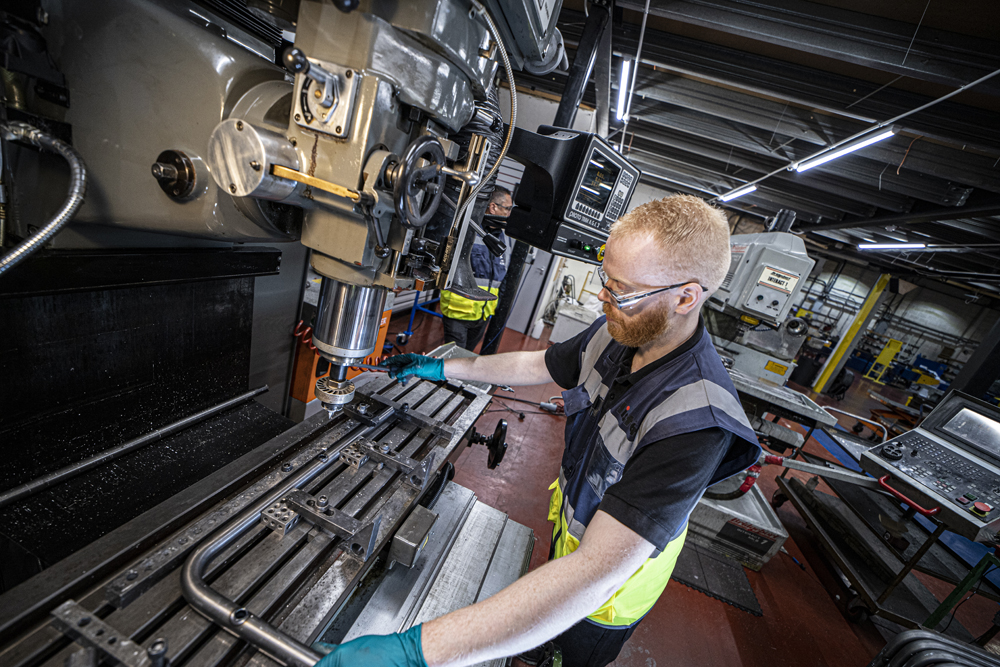
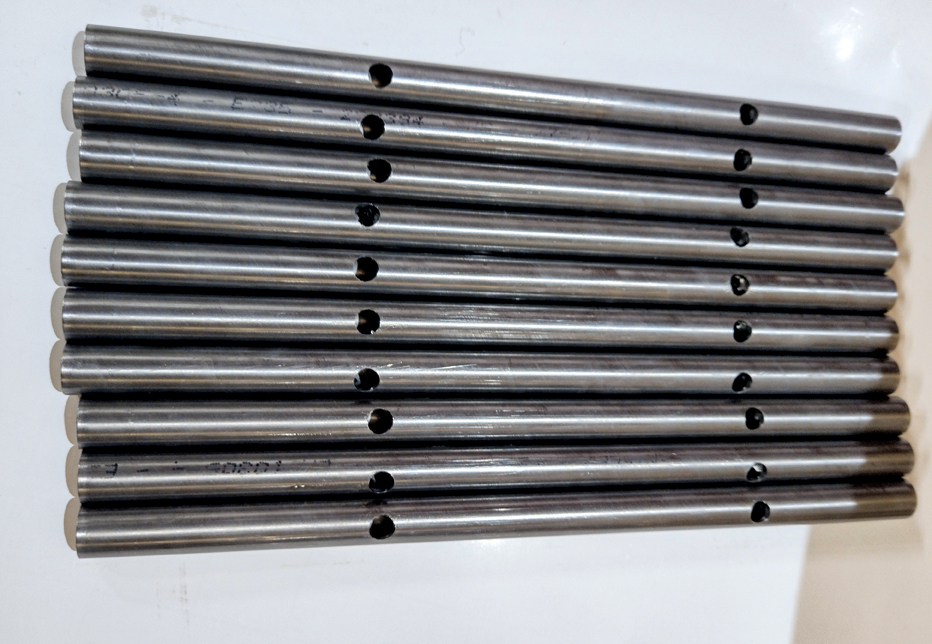
Holes and Slots
If your component has holes or slots, then we would almost always put these in after bending. There are two main reasons for this.
The first
Firstly, if we were to drill a hole before bending, trying to accurately and repeatedly align the angular position of the hole when the tube is loaded into the collet of the bending machine is challenging. This means that the hole may not end up in the correct position relative to the bend plane.
The second
Secondly, the tube bending process distorts the metal. When this is a simple bend on a plain tube, the only effect is a slight thinning of the wall on the outside of the bend and a slight thickening (or bunching up) on the inside of the bend. Normally, this is barely noticeable visually and has only a very small effect on the strength of the component, although if you are going to be using it for high-pressure hydraulic applications, then you should ensure that you choose a suitable wall thickness to begin with. However, if there is a hole anywhere in or near the bend zone, you will see just how much metal can flow. A circular hole suddenly becomes elliptical or, even worse, can act as a tear-propagation point.
 Once the component is bent, if we need to put holes or slots in it, or produce complex cut forms on the ends, then it is almost certain that we have to produce a jig to accurately hold the piece whilst the holes are drilled, milled or laser-cut.
This may be a simple clamp arrangement, or it may be a more complex 3D jig arrangement, depending on the complexity of the component and holes required.
If you only need a round hole, go for that. This can often be produced easily and quickly on a pillar drill. If you require slots or other shapes, it will dictate the more costly process and set-up of either a milling machine or laser cutting machine.
If any holes need threads tapping, we would do that now.
End Forms
The preferred method of end forming would always be both ends (if needed) after bending. The component is typically offered up to the end-forming machine by hand – so no jigging required, even with a complex component. We would only flare one end before bending if it is too short for the flaring tool after bending.
In fact, if both ends require end-forming, then at least one of them must be after bending as the other end needs to be held in the collet of the bending machine.


As a designer, the main issue to be aware of is to leave some clearance from the end form until the first bend. Ideally, this clearance would be the length of twice the diameter of the tube wherever possible.
This is to ensure that there is enough space to avoid the bend fouling the end-form die punch tooling, or to allow space for beading wheels to operate at the end of the tube.
To Conclude
There are further supplementary processes that can be undertaken, such as fitting nuts to the ends of tubes (normally during the end-forming stage), or other forming options such as tube flattening. These are covered in the other guides mentioned previously.
In addition, tube can be painted or plated in various options; please contact us for further details.
By having some understanding of the tube manipulation process and, wherever possible, taking into account some of the key points mentioned previously in this guide, you will be able to follow an effective design for manufacture (DFM) approach in your tubular component development, saving time, cost and resource.
TUBE SELECTION
GUIDE
Find the right materials and tube sizing for your project.